|
I recently decided my 1/48th scale aircraft
collection needed an 80’s era USMC Harrier, and since Hasegawa recently released
a series of new-tooled AV-8Bs, I felt the time had come to do something about
it…
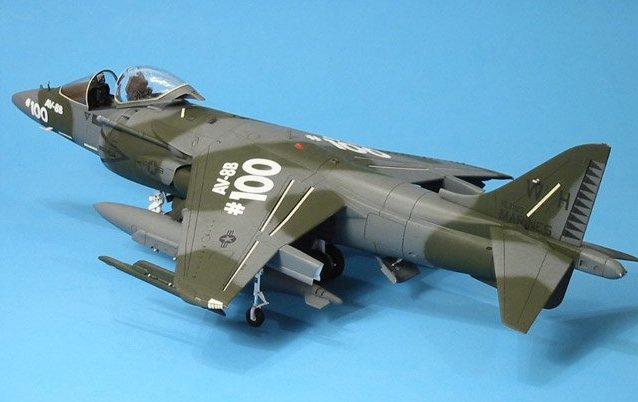
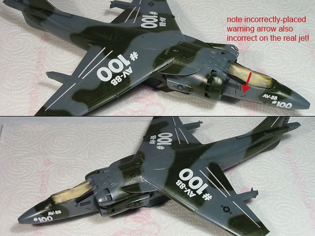
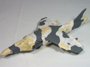
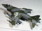
The model I constructed represents the 100th production AV-8B airframe built,
and is marked as it was delivered to VMA-542 in December, 1987. The kit I used
was Hasegawa’s #09538 titled “Desert Harrier”. This version of the AV-8B
includes all the correct bits and pieces needed to build an older, gray/green
Harrier II. In assembling the model, I added parts from the Black Box AV-8B
Harrier II cockpit designed for the Monogram kit, mainly because when I started
the project the Aires Harrier cockpit sets had not yet been released.
|
Click on
images below to see larger images
|
|
|
 |
 |
 |
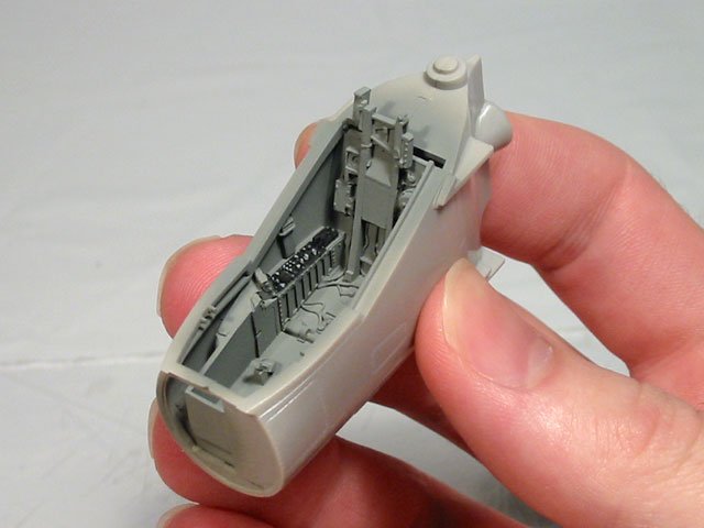
I began with the cockpit and forward
fuselage. Fitting the Black Box cockpit tub was relatively easy. All that was
required was a small amount of sanding at the widest part of the tub to get a
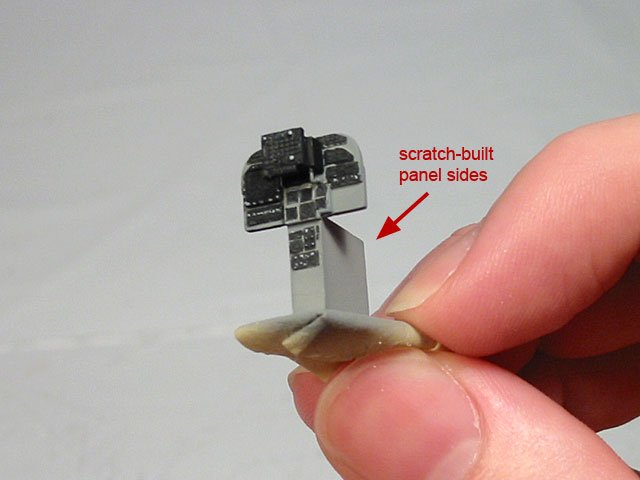
nice fit. Since the slope of the side-mounted control panels is different than
the Monogram kit, the Black Box sidewalls did not work at all, so I removed the
largest details from the resin parts and glued those bits onto the inner walls
of the forward fuselage sides. Also, while working with the forward fuselage
halves, I added the missing rescue door on the starboard side using the
Verlinden scribing template and my handy scriber (a compass needle chucked into
a pin vise).
My reference photos showed that the Harrier instrument panel base had
significant depth to it, so I added some sheet styrene to the kit-provided
instrument panel to replicate this. I would have used the Black Box panel but it
was simply too small to fit into the larger Hasegawa cockpit.
Preparing all the separate, external bits for the model went well. The only real
modification I made was in drilling-out the tie-down rings on the wing-mounted
landing gear struts. They are provided as solid discs out of the box.
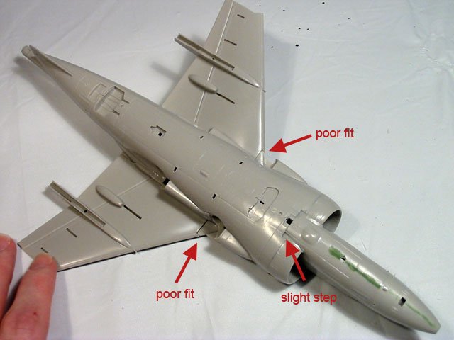
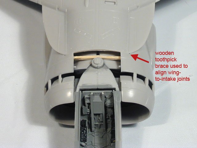
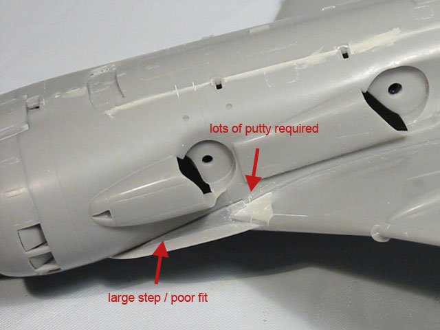
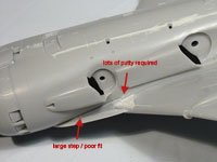
Construction went smoothly until it was time to add the wing assemblies to the
fuselage. Test fitting the pre-assembled wings proved to me that there were
going to be significant fit issues where the undersides of the wings meet the
fuselage. Knowing I was not going to avoid a lot of puttying and sanding here, I
went ahead and attached the wings, concentrating on a good fit on the upper
fuselage. Though working with the fit issues on the underside of the wings was
challenging, everything fell into place once I dug in with my files, putty and
sandpaper.
|
Click on
images below to see larger images
|
|
 |
 |
|
Once all of the main fuselage
parts were added, I began to glue on some of the smaller fuselage bits that
needed to be in place before I started painting the camouflage. This included
the various intake scoops and the refueling probe. Interestingly enough, it
seemed all of these bits needed some extra attention to get everything looking
sharp.
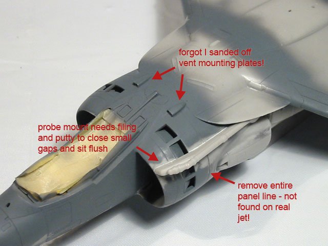
The refueling probe mount does not sit flush on the intake shoulder as molded.
Some careful filing and sanding of the probe mount’s mating surface helped
tremendously, as did a small bead of putty placed along the joint.
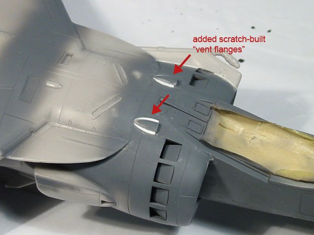
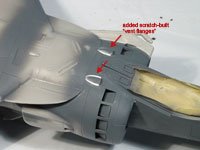
Unfortunately, I added the upper-fuselage intake scoops too quickly, and soon
after, I realized that earlier I had sanded away the molded-on mounting flanges
from the upper fuselage. To fix this, I simply cut two crescent-shaped bits out
of very thin sheet styrene and added them to the sides of each scoop. Once
puttied-in, I was quite happy with the result.
After all the necessary bits were added to the model, it was time to prime,
check the seams, and then paint the camouflage. After I sprayed the primer coat,
I touched up a few areas and filled-in the long, horizontal panel line that
encircles the entire fuselage just behind the intake air-bleed doors. My
reference showed this to be a long line of rivets only.
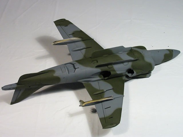
I used Gunship Gray (FS 36118) for the primer and the gray camouflage color. The
gray exterior color used on the real jet was FS 36099, but Gunship Gray is very similar
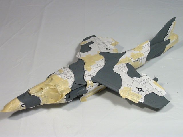
and only a touch lighter in shade. The second camouflage color applied was Dark
Green (FS 34079) which was sprayed after paper paint masks were taped to the entire
airframe. All of the paint used was Testors Model Master enamel sprayed through
my Badger 150 airbrush.
Only a little freehand touch up was necessary after the paint masks were
removed. Once the fine-tuning was complete, I began the decal preparation
process. This consisted mainly of spraying the model with Testors Metalizer
Sealer to give the model a slick finish for better decal adhesion.
Strangely, the markings for this historic airframe have never been available commercially, so
all of the decals with the exception of the aileron/flap tape strips were custom made in Adobe
Illustrator and printed on my ALPS Micro-Dry printer. The tape strips came from
the kit decal sheet.
Once all the painting and decaling was complete, a coat of Future Floor Wax was
sprayed to seal and blend the decals. Next, I washed the panel lines with a mix
of dark
gray craft paint, some water, and a touch of dishwashing liquid. My goal
here was to accent the panels but keep the jet looking fairly clean. Once that dried, I sprayed the model with
a coat of Testors Dullcote mixed with a little talc for extra flatness.
After the final matte coat dried
thoroughly, I began adding all the small fiddly-bits to the model. This is where
I ran into my first serious problem… Once painted, the hot and cold engine nozzles
simply would not clear the fuselage fairings during installation. I cut most of
the locator pin off of each one and I still scratched the finish on all the
nozzles while installing them. To fix the damage, I carefully masked the area
around them and touched them up with sandpaper and my airbrush. Next time, I’ll
likely remove a bit of the plastic from the rear of each nozzle fairing,
effectively shortening each one. This will hopefully add enough wiggle room so I
can add the nozzles without any damage being done.
When installing the landing gear struts, I remembered the problems I
read about regarding the Monogram AV-8B's main landing gear not
being the correct length. Keeping this in mind, I started with the nose and
wing-mounted struts first. Once those were all in place (and with tires mounted
to the nose gear), I
moved on to the center-main gear. Sure enough, I found that the strut assembly was about
one millimeter too short for the wheels to touch the ground. To rectify this, I
simply added some thick cyanoacrylate glue to the strut mounting peg, popped the
gear in place, quickly flipped the jet over from it’s back onto it’s other gear
legs, and using my fingertips, carefully pulled the main gear straight down
until the wheels touched the desk. Luckily, there was plenty of length to the
strut’s mounting peg for adjustment, so this simple procedure worked out fine.
When attempting this, I do suggest doing it before adding any sort of ordnance
to the model. Anything hanging from the wings is just going to get in the way.
The last major trouble-spot I ran into was in working with the clear cockpit
canopy. The sides of the part included in my kit were warped outward, and the
clear plastic contained several hairline cracks. Judging from the damage, I suspect
it had been forcefully removed from the mold. Also, in this series of kits, the
attachment point where the canopy connects to the sprue is quite large, so when
I removed the canopy from the clear sprue, there was a nasty, rough spot left on
the glass that I felt could not be ignored. The attachment point issue was
resolved by carefully sanding away the rough spot and then re-polishing the inside of the
canopy using sandpaper and then Mirror Glaze. The sanding was significant and I actually
ended-up thinning the canopy plastic quite a bit. The best solution I could come up with
for the remaining hairline cracks was to simply dip the canopy in Future (after
the blast cord decal was applied) and hope for the best. This actually did hide
the cracks fairly well.
The last of the many issues with the cockpit canopy was discovered when working
with the canopy blast cord decal. I first added the decal included on the
kit-supplied sheet to the inside of the canopy, but after it was dry, I was not at all
satisfied with the clarity of the surrounding decal film. It was thick and
milky-looking. I soon removed the Hasegawa blast cord, and then applied the
two-piece blast cord decals from a Twobobs Harrier decal sheet. Though it was
very difficult to maneuver such delicate and tiny decals on the canopy, the
result was very pleasing. The film was amazingly clear once it was dry. After
the canopy glass was finally dipped in Future, the surrounding decal film
virtually disappeared.
|
Click on
images below to see larger images
|
|
 |
 |
 |
 |
The last step was to add the
antennas, probes, vents, and the most delicate detail parts which all went on easily and without incident.
I only
made a few modifications at this stage. I thinned-down some of the probes so
they appeared more "in scale". I also formed a canopy grab handle out of copper
wire and added three Waldron jet aircraft mirrors to the canopy bow.
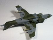
Overall, this was an enjoyable
build. The kit is really quite nice, though the parts breakdown makes the
construction more challenging than what would have been necessary if Hasegawa
didn’t try to create so many different versions of the Harrier using the same
molds. As far as the overall shape, it is very convincing. The only oddities that catch my eye are the
height of the upper-fuselage vent scoops which seem to be a bit too flat, the length of the
cold engine nozzles (they appear to be a bit too narrow and too long compared to
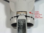
images of the real thing) and the strange gap in the inner intake trunk which I
believe should rest against, and align with, the kit's intake parts. Those issues aside, now that I’ve built one of these Hasegawa Harriers,
I would not hesitate to try another.
Marv
|
|